Friday, January 12, 2007

Exercise2 - Step4

Creating a Custom Entity – Exercise 2 – Step 4

Now you will learn how to add OSNAP points to your custom entity. If you run the application before this step you will see that our custom entity already shows some Object Snap points by default (ENDPOINT and MIDPOINT). In this example we want to add a CENTER object snap to our polyline that will allow users to select the exact center point. To provide this, we need to change the standard behavior of getOsnapPoints() method. This method has 4 signatures and 2 of them, containing the AcGeFastTransform parameter, are for future use. We will use the first signature and will handle the CENTER object snap responding with our center point:

Acad::ErrorStatus AuPolyline::getOsnapPoints (
AcDb::OsnapMode osnapMode,
int gsSelectionMark,
const AcGePoint3d &pickPoint,
const AcGePoint3d &lastPoint,
const AcGeMatrix3d &viewXform,
AcGePoint3dArray &snapPoints,
AcDbIntArray &geomIds) const
{
assertReadEnabled () ;
switch(osnapMode)
{
case AcDb::kOsModeCen:
snapPoints.append(GetPolylineCenter());
break;
}
return (AcDbPolyline::getOsnapPoints (osnapMode, gsSelectionMark, pickPoint, lastPoint, viewXform, snapPoints, geomIds)) ;
}
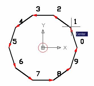
This method receives an Array of points where we need to add the center point whenever the OSNAP CENTER is requested. On line 13 we handle the CENTER object snap by adding our center point to the snapPoints array (Figure 17). Even handling this particular object snap this method needs to call the polyline class level. The polyline will handle all other possible object snaps for us.


Figure 17 – CENTER object snap.

Note: This OSNAP solution handles only simple OSNAP types like CENTER, MIDPOINT and ENDPOINT. Complex OSNAP modes like INTERSECTION require other methods implementations and some additional procedures.

Exercise2 - Step3

Creating a Custom Entity – Exercise 2 – Step 3

Now you will learn how to add GRIP points to your entity. In fact, as the default implementation of AuPolyline forward the call to its base class you may already noted that its GRIP points are visible and working. The GRIP point behavior is handled by two methods. The first method, called getGripPoints() is responsible for acquiring all GRIP points from your entity. The second, called moveGripPointsAt(), is responsible for the action fired by each grip.
Each default polyline GRIP action is to move the related vertex. In this example we want to add one extra grip positioned at our polygon’s center. To do that we first need to create a helper method to calculate this point. We will walk through all polygon points and will sum the coordinates dividing the result by numVerts(). This method will not change our entity data so it is recommended to be CONST and will require only the assertReadEnabled() call:

AcGePoint3d AuPolyline::GetPolylineCenter() const
{
assertReadEnabled();
AcGePoint3d ptC,pti;
double cx = 0.0, cy = 0.0, cz = 0.0;
for (int i=0; i<numVerts(); i++)
{
this->getPointAt(i,pti);
cx += pti[X];
cy += pti[Y];
cz += pti[Z];
}
cx = cx / numVerts();
cy = cy / numVerts();
cz = cz / numVerts();
ptC.set(cx, cy, cz);
return ptC;
}


Lines 04-15 apply the center formula and at line 16 we build the point using cx, cy and cz as the point’s X, Y and Z coordinates respectively.
Next we need to change the default implementation of the both GRIP point methods. First we will redefine the getGripPoints() method. This method has 2 signatures and we will use the new AcDbGripData method instead of the “old style” method.
This method receives an array of AcDbGripData pointers. These objects represent the GRIP point information. We need to inform at least the point and an arbitrary data (void*). This arbitrary data can be used later to get back information from each GRIP point allowing the moveGripPointsAt() method to perform the custom actions:

Acad::ErrorStatus AuPolyline::getGripPoints (
AcDbGripDataPtrArray &grips,
const double curViewUnitSize,
const int gripSize,
const AcGeVector3d &curViewDir,
const int bitflags) const
{
assertReadEnabled () ;
AcDbGripData* gpd = new AcDbGripData();
gpd->setAppData((void*)9999); // Center Grip code
gpd->setGripPoint(GetPolylineCenter());
grips.append(gpd);
AcDbPolyline::getGripPoints (grips, curViewUnitSize, gripSize, curViewDir, bitflags);
return (Acad::eOk);
}


This method will not change our entity’s data so it is also a CONST method and calls assertReadEnabled() method. On lines 09-12 we instantiate an AcDbGripData pointer and set its application data (9999 in this case) and the grip point which is calculated by the GetPolylineCenter() method. Next, on line 13 we forward the call to AcDbPolyline’s grip point method so it is able to add its own GRIP points at last. These GRIP points are those vertexes points we have mentioned before. The next step is to change the moveGripPointsAt() method so when the user clicks on this center GRIP it will reflect a custom action. In this example, our custom action will move the entire polyline. The following code shows how to do that:

Acad::ErrorStatus AuPolyline::moveGripPointsAt (
const AcDbVoidPtrArray &gripAppData,
const AcGeVector3d &offset,
const int bitflags)
{
assertWriteEnabled () ;
for (int g=0; g<gripAppData.length(); g++)
{
// Get grip data back and see if it is our 0 Grip
int i = (int)gripAppData.at(g);
// If it is our grip, move the entire entity. If not, forward the call
if (i == 9999)
this->transformBy(offset);
else
AcDbCurve::moveGripPointsAt (gripAppData, offset, bitflags);
}
return (Acad::eOk);
}


This time, our method cannot be CONST once we will change our entity’s data. Due that, we need to call assertWriteEnabled() at it’s beginning. On line 07 we start to inspect the AcDbVoidPtrArray (an array of void*) looking for our application data (9999). This method also receives a 3D vector which represents the transformation being applied to the GRIP. If the GRIP being modified is our 9999 we will apply this vector transformation to the entire polyline. This can be done through the transformBy() method passing the same vector (Figure 16).


Figure 16 – Center GRIP in action.


If the fired GRIP is not our 9999 code we will forward the call to AcDbCurve class (AcDbPolylin’s base class) which will handle it for us. The resulting behavior is when you select a GRIP over the polyline boundary the entity stretches and when you select the center GRIP the entity moves.

Exercise2 - Step2

Creating a Custom Entity – Exercise 2 – Step 2

Now after you have created a basic custom entity you will learn how to add custom graphics to it. The custom entity’s graphics is generated primarily by the worldDraw() method and optionally by the viewportDraw() method.
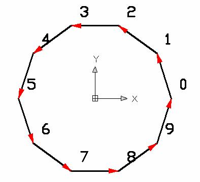
As this entity’s base class already generates a polyline graphic we will add some nice extra graphics to it. Each vertex will receive an index number and an arrow indicating the polyline construction direction (Figure 14).
We will use different colors for each graphic type. The index number will use the 256 color code which is the ByLayer color and the arrows will use a fixed 1 color code which is red. If you change the color of this entity’s layer it will change except on the arrows that will stay red. Further, all arrows will be filled.


Figure 14 – Custom Entity with vertex numbers and arrows


To create these graphics you will need to use some trigonometric methods. The following code demonstrates what you can reach this:


Adesk::Boolean AuPolyline::worldDraw (AcGiWorldDraw *mode)
{
assertReadEnabled();
// Call base class first
AcDbPolyline::worldDraw(mode);
double szRef = 5.0;
// ================================================================
// DIRECTION AND VERTEX NUMBERING
int signal = 1;
double ht2 = szRef/4.0;
for(int i=0; i<numVerts(); i++)
{
AcGePoint3d pti;
this->getPointAt(i,pti);
// Draw vertex text
CString strNum;
strNum.Format(_T("%d"),i);
AcGePoint3d ptTxt = pti + (AcGeVector3d::kXAxis*ht2) + (AcGeVector3d::kYAxis*ht2);
mode->subEntityTraits().setColor(256); // ByLayer
mode->geometry().text(ptTxt, AcGeVector3d::kZAxis, AcGeVector3d::kXAxis, ht2, 1.0, 0.0, strNum);
/
/ Arrow direction
AcGePoint3d ptj;
this->getPointAt(i<(numVerts()-1) ? (i+1) : 0, ptj);
A
cGeVector3d dir = (ptj - pti).normalize();
// Side perpendicular vectors
AcGeVector3d perp = dir;
perp.rotateBy(3.141592/2.0,AcGeVector3d::kZAxis);
AcGePoint3d pt1 = ptj - (dir*ht2) + (perp*(ht2/4.0));
AcGePoint3d pt2 = ptj - (dir*ht2) - (perp*(ht2/4.0));
AcGePoint3d pts[3];
pts[0] = ptj;
pts[1] = pt1;
p
ts[2] = pt2;
// Draw arrow polygon
mode->subEntityTraits().setFillType(kAcGiFillAlways);
mode->subEntityTraits().setColor(1); // red
mode->geometry().polygon(3,pts);
mode->subEntityTraits().setFillType(kAcGiFillNever);
}
//------ Returning Adesk::kFalse here will force viewportDraw() call
return (Adesk::kTrue) ;
}

On line 03 we call the proper assert method which inform what type of access we are executing on this method. As we are not changing any data we need only to READ the entity so we call assertReadEnabled() method. On line 05 we forward up the call to its base class method which will draw the polyline curves. On lines 06-10 we initialize some local variables.
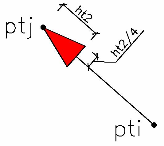
Next, from line 11-39 we perform a loop on each polyline vertex to draw our custom graphics. On lines 13-14 we get the current vertex point. On line range 16-20 we draw the vertex text using the text() geometry primitive at a point with a small displacement related to the vertex point. On lines 22-24 we calculate the end point (ptj) of each polyline segment and its unitary direction vector (dir). Next, on lines 26-33 we calculate the 3 points which will build an arrow head graphic. The perp vector will allow us to draw each side of the arrow head according to the Figure 15. On lines 35-38 we draw the filled arrow head using the polygon() primitive with color red and with the fill type always.

Finally, on line 41, we return Adesk::kTrue to avoid the graphics to be made by the viewportDraw() method.
These classes we have used, with AcGe prefix, are part of the AcGe library which contains several utility classes and methods to help us to deal with geometric calculations. This really helps a lot once most of these calculations are a little bit complex.


Figure 15 – AuPolyline side graphics.

Exercise2 - Step1

Hello,

I will post a sequence of 6 steps of my Exercise 2 provided at last year's AU. It will show you how to create a custom entity inside AutoCAD 2007 using ObjectARX 2007 and Visual Studio 2005.

Hope you enjoy these posts!

Creating a Custom Entity – Exercise 2 – Step 1

You will learn in this exercise how to create a simple custom entity. I will keep it simple as much as I can to reinforce the basic concepts involved. On the next steps we will improve this custom entity by adding great features step by step.
The first step is to name our entity and choose from which base class it will derive. Remember we have to split our application into two modules, an ARX (user interfaces) and a DBX (the custom entity class itself). These two projects will be placed into the same Visual Studio Solution and the ARX module will depend on DBX module. The names will be:


  • Solution: Exercise2 (Visual Studio will create a Exercise2.sln file);

  • DBX Project: AuCustomObjects (Visual Studio will create a AuCustomObjects.vcproj file);

  • ARX Project: AuUserInterface (Visual Studio will create a AuUserInterface.vcproj file);

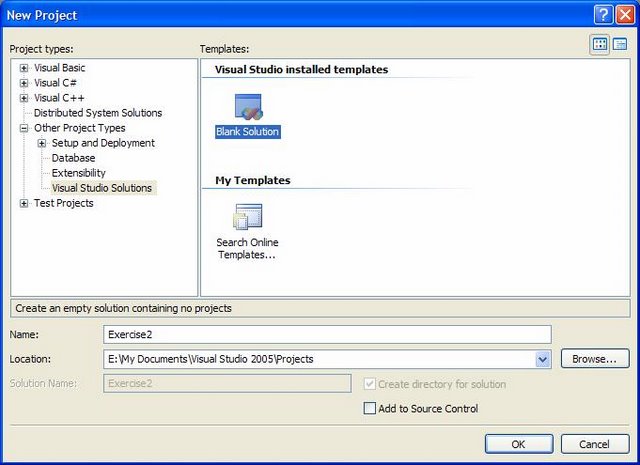
Open Visual Studio, go to the menu File > New Project… Open “Other Project Types” node, click on “Visual Studio Solutions” item. It will show a template called “Blank Solution”. Choose this template and name it as Exercise2 (the location can be any folder you want). Click OK to proceed (Figure 8).
Next, right click the solution icon; select Add and then New Project…, (Figure 9). The dialog, presented on Exercise1 will appear. Select on the list the ObjectARX template and create both AuUserInterface and AuCustomObjects modules. Remember to choose ARX or DBX project type accordingly.
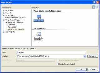


Figure 8 – Blank Solution project

Each project location will be created inside the existing solution by default. Don’t change this location.
Enable MFC option on both projects (don’t need to enable AutoCAD MFC extensions) Enable _DEBUG symbol too. Don’t enable any COM or .NET feature in both projects.
Make AuUserInterface project depend on AuCustomObjects. To do that, right click project AuUserInterface and select Dependencies… Then mark AuCustomObjects project on the list. Click OK.
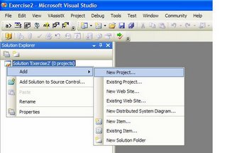

Figure 9 – Creating solution’s projects

Right click project AuUserInterface again and select “Set as Startup Project” (it will turn to bold). Now test your solution building it: go to menu Build > Build Solution. You should get 2 Builds with 0 errors and (1+3) warnings that are safe to ignore.
The final test at this stage is to load the application inside AutoCAD. Remember our project AuUserInterface depends on AuCustomObjects so the DBX module needs to be loaded first than the ARX module. The unload process must be done in reverse order, AuUserInterface first and then AuCustomObjects. You should get everything working this way.
Note: Depending on which type of build you made (Debug or Release) it is recommended to load both projects with the same compilation type.
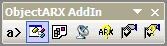
Now we have our DBX and ARX module it is time to add our custom entity’s class. In this example, our entity will be derived from AcDbPolyline which represents the AutoCAD POLYLINE entity. The reason for this option is that our custom entity will behave almost exactly like a polyline but it will add some extra features like vertex numbers, direction symbols, hatch, etc. To add this custom class we will use the Autodesk Class Explorer tool which is located at ARXWizard’s toolbar. It is the second button like the Firgure 10 shows.
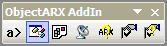

Figure 10 – ARXWizard toolbar

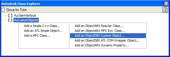
Once you click on this button a dialog bar will appear allowing you to explore all existing classes into your projects. At this time, there are no custom entity classes available. Select our DBX module and then right click on it. A pop-up menu will be displayed. Select the “Add an ObjectDBX Custom Object” option (Figure 11).
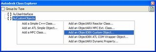

Figure 11 – Autodesk Class Explorer

This wizard has 3 steps. The first step, called Names (Figure 12), allows you to specify all basic custom entity’s features. First, name it as “AuPolyline”. Choose as base class the AcDbPolyline class (note you have several other classes available to derive from). Remaining fields will be filled automatically. Press Next.
Once you select the polyline as your base class you are saying that your custom entity will behave like a polyline except where you redefine it. This is done through the virtual methods I have mentioned before.


Figure 12 – Custom Object Wizard - Names

The Custom Object Wizard also will help you to implement basic class features. This is done on the second step of this Wizard, called Protocols. Enabling these options will instruct the wizard to add the related virtual methods simplifying the class creation process for you.

Inside this dialog you can specify if your entity participate on DWG/DWF protocols, if your entity implements OSNAP points, GRIP points and viewport dependent graphics and, at last, if it implements curve protocols. In this example we will enable only DWG protocol and all 3 AcDbEntity protocols which will allow us to implement some basic features (Figure 13).
The third step, called Advanced, will allow you to add notification and cloning features to your custom entity. In this example we will not use these features. There are many other features you can redefine through a huge set of virtual methods but to keep this example simple we will only implement these ones.
Click Finish to create your Custom Entity’s Class. Remember, it will be placed at you DBX module.


Figure 13 – Custom Object Wizard - Protocols

The Custom Entity Wizard will create default virtual methods but, in this particular case, our base class AcDbPolyline does not support all of these methods signatures. If you compile the solution you will get 4 error messages exactly due that. For now, we will replace the explicit AcDbPolyline:: prefix on these 4 return calls by AcDbCurve:: prefix which is the AcDbPolyline base class. Now you should get no errors.
If you inspect your projects Solution Explorer you will note two new files: AuPolyline.h and AuPolyline.cpp. These files, inside your DBX module, are responsible to declare and implement your custom entity. Open these two files and walk through the generated code.
Now you need to add a new command, inside your ARX module, to create an instance of your new custom entity. To do that, on the Solution Explorer, right click the AuUserInterface project and click “Set as Startup Project” (project name will turn to bold). Now, click on the first icon of ARXWizard toolbar (a icon with “a>” text). This button will open the “ObjectARX Commands” dialog box. It has two command lists. Right click the first list and select New. A new line will be added to this list with a default command called “MyCommand1”. Click OK.
If you open the acrxEntryPoint.cpp file of AuUserInterface project you will find, inside class CAuUserInterfaceApp, the AuUserInterface_MyCommand1() empty method which will be called when you fire MYCOMMAND1 command inside AutoCAD. Inside this method you will create an instance of your AuPolyline entity.
Remember that your custom entity class implementation is located into the DBX project. Due that you will need to add (through #include compiler instruction) a reference to the AuPolyline class declaration file. To do that, add the following compiler instruction at the beginning of acrxEntryPoint.cpp file of your ARX module right after #include "resource.h" line:

#include "..\AuCustomObjects\AuPolyline.h"
The “..\” part of this include path goes up one folder level (getting back to the Solution’s root folder) and then goes into the DBX project folder. Now you can compile your project and shouldn’t get any errors. Next, open AutoCAD, load first the DBX module and then the ARX module (there will be two text messages at AutoCAD command prompt confirming that the both load processes were succeeded. Type your project’s command “MYCOMMAND1” and run a ZOOM EXTENTS command to see the generated entity. If you also run the LIST command and select this entity you will see its detailed information.
The following code will create a 10 sided polyline (closed) and will add it to the Model Space Block Table Record.

// - AuUserInterface._MyCommand1 command (do not rename)
static void AuUserInterface_MyCommand1(void)
{
// AuPolyline entity
AuPolyline* pL = new AuPolyline();
int nSides = 10;
double incAngle = 2*3.141592 / nSides;
// Add vertex list
for (int i=0; i<nSides; i++)
pL->addVertexAt(i,AcGePoint2d(10*cos(i*incAngle),10*sin(i*incAngle)));
// Set Polyline as closed
pL->setClosed(Adesk::kTrue);
// open the proper entity container
AcDbBlockTable* pBT = NULL;
AcDbDatabase* pDB = acdbHostApplicationServices()->workingDatabase();
pDB->getSymbolTable(pBT,AcDb::kForRead);
AcDbBlockTableRecord* pBTR = NULL;
pBT->getAt(ACDB_MODEL_SPACE, pBTR, AcDb::kForWrite);
pBT->close();
// now, add the entity to container
AcDbObjectId Id;
pBTR->appendAcDbEntity(Id, pL);
pBTR->close();
pL->close();
}

On lines 05-07 we instantiate the entity and initialize some local variables. Next, on lines 9-10 we add a list of vertexes to the entity. Line 12 set the polyline as closed. On lines 14-19 we open the AutoCAD database, open the Block Table container and then get the Model Space container. On lines 21-24 we add our entity do Model Space and then close it and the entity itself.
Note: You cannot delete the entity’s pointer once it is added to AutoCAD database. In this case its management is delegated to AutoCAD and you only need to call the close() method. If you delete this pointer you will cause AutoCAD to crash.
Friday, December 15, 2006

Hello,

I'm sure you probably have faced a situation where you perform some heavy calculations inside AutoCAD with or without a dialog running. In these cases AutoCAD may look frozen and this may look strange to the user because it may think AutoCAD has really frozen and then the user may try to close it.

Even if you use a progress bar like AutoCAD status bar if you change the current window and get back to AutoCAD it may look frozen in black/white colors.

This occurs because the processor focus all its resources into your heavy loop and does not save enough time to both AutoCAD and your dialog process its own messages. These messages will affect several things like, for instance, the dialog graphics update.

The below function will let AutoCAD do this and you may call it from inside your loop (maybe a FOR or WHILE heavy statements). This way, on each interaction, this function will let AutoCAD process its messages.

void PumpAcadMessages()
{
// Get AutoCAD application
CWinApp* app = acedGetAcadWinApp();
// Get Main window
CWnd* wnd = app->GetMainWnd();
// dispatch incoming sent messages

MSG msg;
while (::PeekMessage (&msg, wnd->m_hWnd, 0, 0, PM_NOREMOVE))
{
// if can't pump, break
if (!app->PumpMessage())
{
::PostQuitMessage(0);
break;
}
}
LONG lIdle = 0;
// Now it's time to MFC do the work
while (app->OnIdle(lIdle++));
}

If you also would like to process your dialog messages you just need to change the first two lines and use your dialog's CWnd pointer instead of AutoCAD window's pointer.

Cheers!

Thursday, December 14, 2006

AU2006 was fantastic!

Hello,

Au2006 was amazing. There were almost 7500 people this year and several classes were provided.
If you would like to check those classes visit AU Online at: http://www.autodesk.com/auonline

I will post some content of my class but I need first to reorganize its topics and pictures.
Stay tuned.

Cheers!

Monday, August 07, 2006

AU 2006

Hello,

Autodesk University 2006 registration is now open!

AU 2006

I'm glad to inform you that this year I have been accepted as Speaker. My 1,5 hour class will be about Custom Entities. Class code is CP33-3 and more information can be found here:

The Power of ObjectARX(R) - CP33-3

Hope to meet you in Las Vegas!
Regards,
Fernando.

Friday, August 04, 2006

Chat Sessions

Hello,

I have recently added a new button at my Blog to allow chat conversations.
The idea is to schedule some chat sessions with users to discuss specific subjects.
You may start to send me your subject suggestions by e-mail so I can start to create a schedule for the chat sessions.

As I always did all information at this Blog is free as any other provided tools. The idea is to keep this site alive with Google ads and now with "Make Donation" button.

Cheers!
Fernando.

Thursday, July 06, 2006

New Blog about AutoCAD programming

Hello,

Finally we have now an Autodesk Blog about ObjectARX/.NET programming!

Kean Walmsley, Senior Manager of our worldwide DevTech team, has started a blog dedicated to programmers working with Autodesk technologies

Congratulations to Kean Walmsley.

http://through-the-interface.typepad.com

Fernando.

Wednesday, May 17, 2006

Adding your own Status Bar Button

Introduction

Hello,

Sometimes you need to have a quick access to your command mainly when this one is about enable/disable something in your software. Using ObjectARX you can easily add a new button to existing AutoCAD Status Bar.

To add this new button to AutoCAD Status Bar we need to derive a new class from AcPane and add our desired appearence and behavior. In this example I will show you how to create a simple ON/OFF button.

How to Begin

Create a new ARX project using ARXWizard. Add a new empty file called MyPane.h and use the follwoing code:

#pragma once
#include "AcStatusBar.h"
class MyPane : public AcPane
{
public:
// ----------------------
MyPane(void)
{
this->SetToolTipText(_T("This is MyPane Button"));
this->SetText(_T(" MyPane [OFF] "));
this->SetStyle(ACSB_POPOUT);
enabled = false;
}
// ----------------------
virtual ~MyPane(void) {;}
// ----------------------
virtual void OnLButtonDown(UINT nFlags, CPoint point)
{
AcPane::OnLButtonDown(nFlags,point);
enabled = !enabled;
CString strLabel;
strLabel.Format(_T(" MyPane [%s] "),enabled ? _T("ON") : _T("OFF"));
this->SetText(strLabel);
this->SetStyle(enabled ? ACSB_NORMAL : ACSB_POPOUT);
AcApStatusBar* pStatus = acedGetApplicationStatusBar();
if (pStatus) pStatus->Update();
}
// ----------------------
virtual void OnRButtonDown(UINT nFlags, CPoint point) {;}
// ----------------------
virtual void OnLButtonDblClk(UINT nFlags, CPoint point) {;}
// ----------------------

private:
bool enabled;
};


In this example we are supporting only the LEFT BUTTON CLICK event. Note that you may support other events too. We have added a bool member to handle the switching between ON / OFF states.

After that we need to add this button when our application starts. Open your acrxEntryPoint.cpp file and add the following include:

#include "MyPane.h"

Now, add a MyPane pointer variable as a member of your application class:

MyPane* pMyPane;

Next, add the following two functions to your application class:

// ----------------------
void AddMyPaneButton()
{
AcApStatusBar* pStatus = acedGetApplicationStatusBar();
if (pStatus) {
pMyPane = new MyPane();
pStatus->Add(pMyPane);
}
}
// ----------------------
void RemoveMyPaneButton()
{
AcApStatusBar* pStatus = acedGetApplicationStatusBar();
if (pStatus && pMyPane) pStatus->Remove(pMyPane);
}
// ----------------------


Finally, we need to call these two functions from inside the kInitAppMsg and kUnloadAppMsg events:

// ----------------------
virtual AcRx::AppRetCode On_kInitAppMsg (void *pkt) {
AcRx::AppRetCode retCode =AcRxArxApp::On_kInitAppMsg (pkt) ;
AddMyPaneButton();
return (retCode) ;
}
// ----------------------
virtual AcRx::AppRetCode On_kUnloadAppMsg (void *pkt) {
AcRx::AppRetCode retCode =AcRxArxApp::On_kUnloadAppMsg (pkt) ;
RemoveMyPaneButton();
return (retCode) ;
}
// ----------------------


That's it. Now if you load your ARX application you will see a new Status Bar Button. Try it to switch between ON/OFF. Cool?

Fernando.

Sunday, May 14, 2006

User's Samples and Articles

Hello,

I have created a section at this Blog dedicated to all users that would like to send some samples and articles they want to share.

All articles and samples are supported and are responsibility of its authors.

The first article is from Nikolay N. Poleshchuk, a russian AutoCAD author, about a transparent splash screen.

Feel free to send me your articles and samples.

Regards,
Fernando.

Transparent Splash Screen

Transparent Splash Screen As a Modeless Dialog[1]

We would like the splash screen window automatically disappear e.g. after five seconds period. It would be good if an impatient user could close it by a click in the client area.
Moreover it is interesting for the splash screen to be transparent and we could see the current drawing entities under it. Transparency can be reached by Opacity property of the windows created with Windows Forms.

Create a new ObjectARX project named Book16 with the preferences as in the prevoius project[2].

Add book16 LISP function that would be called as ads_book16 C-function defined in acrxEntryPoint.cpp file (see listing 5.34).

Listing 5.34. The ads_book16 function

// Based on:
// N.Poleshchuk, Chapter 05\Book16\acrxEntryPoint.cpp
// In the book "AutoCAD: Application Development, Tuning and// Customization"
// (BHV-Petersburg Publishing House. Russia, 2006)
// http://poleshchuk.spb.ru/cad/eng.html
//
// ----- ads_book16 symbol (do not rename)
static int ads_book16(void)
{
splash16();
acedRetVoid () ;
return (RSRSLT) ;
}

splash16 will be a managed code function. Add to the project Splash16.h and Splash16.cpp files (declaration and body of the splash16 function) and insert #include "Splash16.h" statement at the beginning of the acrxEntryPoint.cpp file.
The Splash16.h file besides splash16 declaration will contain Wform16 class definition for a dialog box. Code for the Splash16.h file is given in listing 5.35.

Listing 5.35. The Splash16.h file

// Based on:
// N.Poleshchuk, Chapter 05\Book16\Splash16.h
// In the book "AutoCAD: Application Development, Tuning and// Customization"
// (BHV-Petersburg Publishing House. Russia, 2006)
// http://poleshchuk.spb.ru/cad/eng.html
//
#pragma once
#using <system.drawing.dll>
#using <system.windows.forms.dll>


#include "StdAfx.h"
using namespace System;
using namespace System::Drawing;
using namespace System::Windows::Forms;

void splash16();

public __gc class Wform16: public Form
{
public:
Wform16();
protected:
void OnTimerTick(Object *sender, System::EventArgs *ea);
void OnClick(Object *sender, System::EventArgs * ea);
};

Besides splash16 function prototype the Splash16.h file contains description of a managed class derived from the standard Form class. There are three member functions in the class:


  • Wform16 — Wform16 class constructor;
  • OnTimerTick — function handling the timer event (timer signal);
  • OnClick — function handling the second event (click in the client area of the dialog box).
Splash16.cpp file (shown in listing 5.36) includes all the function implementations.

Listing 5.36. The Splash16.cpp file

// Based on:
// N.Poleshchuk, Chapter 05\Book16\Splash16.cpp
// In the book "AutoCAD: Application Development, Tuning
// and Customization"
// (BHV-Petersburg Publishing House. Russia, 2006)
// http://poleshchuk.spb.ru/cad/eng.html
//
#include "StdAfx.h"
#include "Splash16.h"

using namespace System::Drawing;
using namespace System::Windows::Forms;
using namespace Autodesk::AutoCAD::ApplicationServices;

void splash16()
{
Wform16* pwf = new Wform16();
Autodesk::AutoCAD::ApplicationServices::Application::
ShowModelessDialog(pwf);
}

Wform16::Wform16()
{
// Dialog box parameters
Size = System::Drawing::Size(370, 300);
StartPosition = FormStartPosition::Manual;
Location = Point(300, 150);
BackColor = Color::Aquamarine;
Opacity = 0.5;
FormBorderStyle = FormBorderStyle::None;

// Font
FontFamily *pFf = new FontFamily(L"Arial");
System::Drawing::Font *pFont = new System::Drawing::Font(pFf, 36, FontStyle::Bold);

// Text in the middle of the window
Label *pTxt1 = new Label();
pTxt1->Text = S"Book16";
pTxt1->Location = Point(90, 120);
pTxt1->AutoSize = true;
pTxt1->ForeColor = Color::Black;
pTxt1->Font = pFont;
Controls->Add(pTxt1);

// Handler of the Click event for the form
this->Click += new EventHandler(this, &Wform16::OnClick);

// Timer creation
System::Windows::Forms::Timer *tm = new Timer();
tm->Interval = 5000; // Signal interval
tm->Tick += new EventHandler(this, &Wform16::OnTimerTick);
tm->Enabled = true;
}

void Wform16::OnClick(Object *sender, System::EventArgs *e)
{
// by click close the window
Wform16::Close();
}

// Reaction to the first (and the last) timer signal
void Wform16::OnTimerTick(Object *sender, System::EventArgs *ea)
{
System::Windows::Forms::Timer *t1 =
static_cast (sender);
// Timer stop
t1->Stop();
// Close the window after the first signal
Wform16::Close();
}

splash16 function creates an instance of the dialog class and opens the splash screen window with the special ShowModelessDialog method in modeless mode. The dialog object is deleted as a result of watching two events: Tick (timer signal) and Click (click inside window but not on the text). Standard event list is reviewed in the next section.

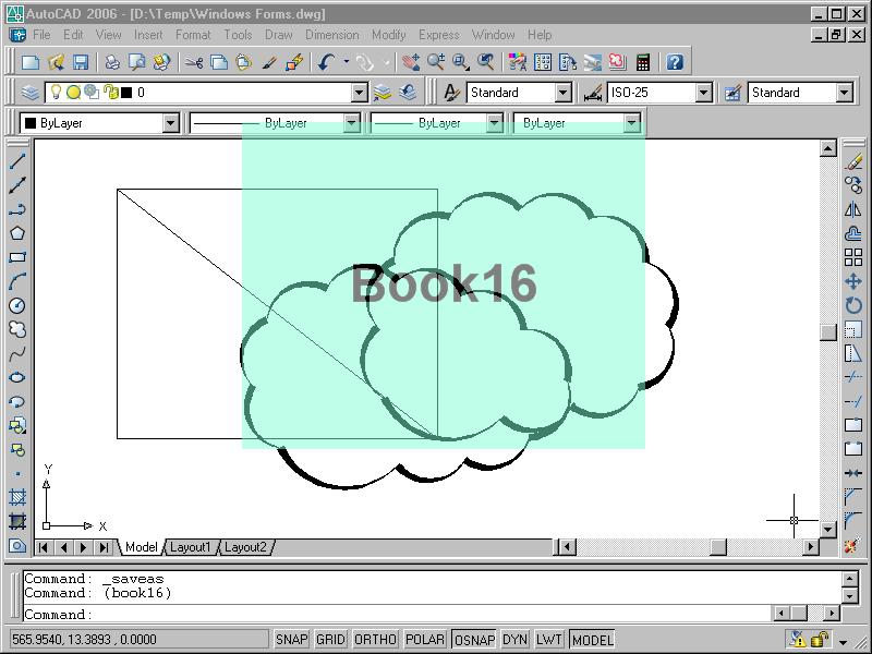
Pic. 5.63 shows splash screen of our application over the current drawing background. The window is opened by the LISP expression (book16), entered in the AutoCAD command line.


Pic. 5.63. Window with transparent splash screen

This transparent window looks like the window being shown while starting AutoCAD session.
Let’s consider window constructor (Wform16::Wform16 function in the Splash16.cpp file). At first window parameters are being defined. The Size, StartPosition, Location and BackColor properties sense is familiar to us from the previous example[3].
The Opacity property sets the opacity ratio. It can take real values from 0 to 1. When 1 — the window is opaque, when 0 — absolutely transparent (and not seen). We use an average value (0.5).

The FormBorderStyle property is set to None that is a member of the FormBorderStyle enumeration. It means that the window has neither frame nor caption (as the AutoCAD splash screen has).

To place an inscription in the center of the window it is necessary to prepare the font. That is why the FontFamily and Font class instances are created. The font is used in the Label class instance which is added by the Add method to the Controls collection of the dialog.
The next constructor text line adds the Click event handler, that is a click inside the form (but not on the text control having its own Click event):

this->Click = new EventHandler(this, &Wform16::OnClick);

Event handler is an object representing the EventHandler class. Using the above text line we connect the object with a delegate (i.e. pointer to the Wform16::OnClick function). This is the function that will be called if event occured.

The Wform16::OnClick function has a very simple body — only Close method is run. That’s why after click inside the form the splash screen closes.

The last four statements in the constructor create a timer with definite features. The timer that issues signals with some frequency is an object of the Timer class. The FCL[4] classes with the same names exist in three namespaces: System.Timer, System.Threading and System.Windows.Forms. In our Book16 project we chose the last class.
When creating a timer at last the two properties should get their values:

  • Interval — time slot, after which the timer signals; the slot is measured in milliseconds, therefore 5000 value corresponds to 5 seconds of the real time;
  • Enabled — timer state; the true value is obligatory to activate the timer object.
The following line creates a handler of the Tick event (timer signals in given time slots):

tm->add_Tick(new EventHandler(this,&Wform16::TimerOnTick));

The first timer signal must be emitted in five seconds after start. This signal also must become the last one: the Wform16::TimerOnTick function stops the timer (Stop method is used) and closes the dialog box.

The timer should be stopped (another way is to set false to Enabled property), else after that garbage collector will free the memory used by the timer.

So in our sample the splash screen appears in a modeless mode (that is we may do some drafting in the document while seeing the splash) and disappears if the user clicks it or five seconds pass after start.

If there is a nonzero probability of launching the second copy of the splash screen then it is useful to add to our program the analysis of our splash screen presence in the main memory (it is sufficient to create a corresponding global variable and to check its value).

Event handling

Adding controls to the form and their event handling were considered in the previous section[5] Book16 sample project. Now we will emphasize some moments. For example we will take the Button control which is a button of our dialog box.
In order to add a button to a dialog we must create a new instance of the corresponding class:

Button *bt = new Button();

After this it is possible to set values to the properties, e.g.: Text, Size, Location, BackGroundImage, BackColor, ForeColor, Font etc. The created object is then included into collection of the form controls:

Controls->Add(bt);

Each class is connected with many standard events that could be handled programmatically (your own events can be created too). Let’s mention some of the Button control events:


  • BackColorChanged — button background color was changed;
  • Click — there was a click on the button;
  • DragEnter — an object was dragged to the button;
  • ForeColorChanged — text color was changed;
  • GotFocus — button received focus;
  • KeyDown — key was pressed while button had focus;
  • MouseDown — mouse button was pressed when cursor was over the button;
  • MouseUp — mouse button was released when cursor was over the button;
  • VisibleChanged — button visibility state changed (connected with Visible property).
We must create an event callback function that will be called to analyze event parameters and running some actions. Mostly function names look like event names. For example we can expect that for Button object Click event the function name will be OnClick, OnButtonClick or OnBtClick.

Each of the selected events must be connected with the handler that is an object of the EventHandler class. Namely this handler calls necessary function if event occurs.
E.g. if we build for the Click event a handler that should call Wform16::OnBtClick function then the statement for the handler creation in the Wform16 form class constructor body will be as follows:

add_Click(new EventHandler(this, &Wform16::OnBtClick));

Just the same in a more modern manner (using overloaded += operator):

bt->Click += new EventHandler(this, &Wform16::OnBtClick);

Some events (for example Paint) have another form of the same thing:

Paint += new PaintEventHandler (this, OnPaint);

The last form looks like adding event handler in C# language (see chapter 7[6]).
Every callback function receives two arguments: pointer to an object whose event was generated and additional event data. For example:

void Wform16:: OnTimerTick(Object *sender, System::EventArgs *ea)

The first argument has universal System::Object* type therefore while applying we must bring it to the necessary type (use static_cast operator, see listing 5.36).

Downloads

http://poleshchuk.spb.ru/cad/Download/Book16eng-2002(AutoCAD2006).zip
http://poleshchuk.spb.ru/cad/Download/Book16eng-2005(AutoCAD2007).zip
English Download page is accessible by link http://poleshchuk.spb.ru/cad/Downloade.htm

[1] N.Poleshchuk “AutoCAD: Application Development, Tuning and Customization”, pp. 449–455.
[2] The previous project was created with ObjectARX Wizard using .NET mixed managed code support. (Author’s note)
[3] They define the size, coordinates and background color of the window. (Author’s note)
[4] Framework Class Library.
[5] Opaque Splash Screen As a Modal Dialog. (Author’s note)
[6] Chapter 7. Fortran, Delphi, C#, VB etc. (Author’s note)


Tuesday, May 09, 2006

Using MACROS inside ObjectARX

Hello,

Sometimes is very tedious to create functions to access your custom object members. In some situations we also forget to call the proper assert method before edit or read the variable. This can cause you some trouble later.

I have decided to make a bunch of macros to make our life easier. Using these macros you can speed up your development.

How to use:

First, place the following macros inside a general .H file, say ArxMacros.h, and place it inside your project:

#define _ARX_SGET(x) LPCTSTR Get##x(void) const { assertReadEnabled(); return _s##x; }
#define _ARX_SSET(x) void Set##x(LPCTSTR sValue) { assertWriteEnabled(); _s##x.Format("%s", sValue); }
#define _ARX_IGET(x) int Get##x(void) const { assertReadEnabled(); return _i##x; }
#define _ARX_ISET(x) void Set##x(int iValue) { assertWriteEnabled(); _i##x = iValue; }
#define _ARX_BGET(x) BOOL Get##x(void) const { assertReadEnabled(); return _b##x; }
#define _ARX_BSET(x) void Set##x(BOOL bValue) { assertWriteEnabled(); _b##x = bValue; }
#define _ARX_FGET(x) float Get##x(void) const { assertReadEnabled(); return _f##x; }
#define _ARX_FSET(x) void Set##x(float fValue) { assertWriteEnabled(); _f##x = fValue; }
#define _ARX_DTGET(x) COleDateTime Get##x(void) const { assertReadEnabled(); return _dt##x; }
#define _ARX_DTSET(x) void Set##x(COleDateTime dtValue) { assertWriteEnabled(); _dt##x = dtValue; }
#define _ARX_LGET(x) long Get##x(void) const { assertReadEnabled(); return _l##x; }
#define _ARX_LSET(x) void Set##x(long lValue) { assertWriteEnabled(); _l##x = lValue; }
#define _ARX_DGET(x) double Get##x(void) const { assertReadEnabled(); return _d##x; }
#define _ARX_DSET(x) void Set##x(double dValue) { assertWriteEnabled(); _d##x = dValue; }
#define _ARX_OBJIDGET(x) AcDbObjectId Get##x(void) const { assertReadEnabled(); return _id##x; }
#define _ARX_OBJIDSET(x) void Set##x(AcDbObjectId lValue) { assertWriteEnabled(); _id##x = lValue; }
#define _ARX_PT3DGET(x) const AcGePoint3d& Get##x(void) const { assertReadEnabled(); return _pt##x; }
#define _ARX_PT3DSET(x) void Set##x(AcGePoint3d ptValue) { assertWriteEnabled(); _pt##x = ptValue; }
#define _ARX_PT2DGET(x) const AcGePoint2d& Get##x(void) const { assertReadEnabled(); return _pt##x; }
#define _ARX_PT2DSET(x) void Set##x(AcGePoint2d ptValue) { assertWriteEnabled(); _pt##x = ptValue; }


Go to your custom object's class header and place them as follows:

_ARX_SGET(Name)
_ARX_SSET(Name)
_ARX_DGET(Number)
_ARX_DSET(Number)
_ARX_PT3DGET(Point)
_ARX_PT3DSET(Point)

When you compile the code these macros will expand as follows:
void SetName(LPCTSTR sValue);
LPCTSTR GetName(void) const;

void SetNumber(double dValue);
double GetNumber(void) const;

void SetPoint(AcGePoint3d ptValue);
const AcGePoint3d& GetPoint(void) const;

As they refer to local class variable we need to add them will proper naming convention (note that I put a prefix on each variable inside macros using a letter to identify its type):

CString _sName;
double _dNumber;
AcGePoint3d _ptPoint;

You don't need to place anything else inside your class CPP file. Of course if you need a special behavior when accessing your members you will need to fully create the access function.

That's it, now you have your access functions ready to use.

Fernando.

Wednesday, March 01, 2006

AutoCAD 2007

Hello,

Today, 1st March 2006, all beta sites are allowed do discuss about the next release of AutoCAD.
Named AutoCAD 2007 it will present several exciting new features specially on 3D, Visualization and Render engines.

Regarding to the programming side, there are several and important issues related to this new release. I will discuss them further but I would present below a brief introduction about these impacts:
  • Binary Compatibility Break: AutoCAD 2007 is being compiled with new Visual Studio 2005 which uses MFC 8.0 and .NET Framework 2.0. This will cause a binary break on your ObjectARX applications and they will need to be recompiled with the new ObjectARX 2007 SDK and Visual Studio 2005. Once you compile your application with the new ObjectARX 2007 SDK you can't load it on previous version so, for a couple of years and until your clients don't upgrade too, you will need to live with two releases using side by side versions of AutoCAD, ObjectARX and Visual Studio;
  • UNICODE support: AutoCAD 2007 requires that your ObjectARX application fully support and use unicode. This will require a full review in your code converting all non-unicode string variables and calls to unicode. This can take long time depending on how your code strings are used and organized;
  • New Solid and 3D API: AutoCAD 2007 brings several features on 3D solids modeling and 3D visualization. The Render engine was totally redesigned and now supports new types of materials, tranparency, visual styles and much more;
  • Several .NET API improvements: New CUI API and Tool Palette Management. AutoLISP interoperability from .NET (now you can call LISP function and send/receive parameters from .NET).

There are much more and you really need to see by yourself.

I'm working on a new set of tutorials and documents to explore the new Visual Studio 2005 compiler, ObjectARX 2007 and AutoCAD 2007. Stay tuned for the upcoming articles.

As soon as the AutoCAD 2007 is released Autodesk will make available the new ObjectARX 2007 SDK for downloading. Stay tuned on Autodesk website during the next days.

Cheers!
Fernando Malard.

Monday, August 08, 2005

Contest cancelled

Hello,
Our contest was cancelled because no application was submitted.
To allow other users to also participate, we have changed the Contest as follows:

- The contest will be about applications developed with ObjectARX (don't need to show AutoCAD 2006 new features anymore);
- The contest will be opened only through AUGI (Autodesk User Group International);
- Users who want to participate will need to register at AUGI (www.augi.com) and register to ATP086 (ObjectARX for Dummies) class (http://www.augi.com/education/schedule.asp)
- At the end of this ATP course we will judge the best ObjectARX application;

Kindest regards,
Fernando.

Wednesday, July 13, 2005

Contest registration postponed

Hello,

I would like to announce that the key dates of our Contest has been postponed.
New key dates are:

Registration and application deploy: July, 29
Contest results: August, 5

Hope this give more time to users decide to participate on this Contest.
Invite your friends to participate too!
Remember, we are providing 2 copies of AutoCAD 2006 (NFR)!

Cheers!
Fernando.