Now after you have created a basic custom entity you will learn how to add custom graphics to it. The custom entity’s graphics is generated primarily by the worldDraw() method and optionally by the viewportDraw() method.
As this entity’s base class already generates a polyline graphic we will add some nice extra graphics to it. Each vertex will receive an index number and an arrow indicating the polyline construction direction (Figure 14).
We will use different colors for each graphic type. The index number will use the 256 color code which is the ByLayer color and the arrows will use a fixed 1 color code which is red. If you change the color of this entity’s layer it will change except on the arrows that will stay red. Further, all arrows will be filled.
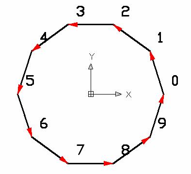
Figure 14 – Custom Entity with vertex numbers and arrows
To create these graphics you will need to use some trigonometric methods. The following code demonstrates what you can reach this:
Adesk::Boolean AuPolyline::worldDraw (AcGiWorldDraw *mode)
{
assertReadEnabled();
// Call base class first
AcDbPolyline::worldDraw(mode);
double szRef = 5.0;
// ================================================================
// DIRECTION AND VERTEX NUMBERING
int signal = 1;
double ht2 = szRef/4.0;
for(int i=0; i<numVerts(); i++)
{
AcGePoint3d pti;
this->getPointAt(i,pti);
// Draw vertex text
CString strNum;
strNum.Format(_T("%d"),i);
AcGePoint3d ptTxt = pti + (AcGeVector3d::kXAxis*ht2) + (AcGeVector3d::kYAxis*ht2);
mode->subEntityTraits().setColor(256); // ByLayer
mode->geometry().text(ptTxt, AcGeVector3d::kZAxis, AcGeVector3d::kXAxis, ht2, 1.0, 0.0, strNum);
// Arrow direction
AcGePoint3d ptj;
this->getPointAt(i<(numVerts()-1) ? (i+1) : 0, ptj);
AcGeVector3d dir = (ptj - pti).normalize();
// Side perpendicular vectors
AcGeVector3d perp = dir;
perp.rotateBy(3.141592/2.0,AcGeVector3d::kZAxis);
AcGePoint3d pt1 = ptj - (dir*ht2) + (perp*(ht2/4.0));
AcGePoint3d pt2 = ptj - (dir*ht2) - (perp*(ht2/4.0));
AcGePoint3d pts[3];
pts[0] = ptj;
pts[1] = pt1;
pts[2] = pt2;
// Draw arrow polygon
mode->subEntityTraits().setFillType(kAcGiFillAlways);
mode->subEntityTraits().setColor(1); // red
mode->geometry().polygon(3,pts);
mode->subEntityTraits().setFillType(kAcGiFillNever);
}
//------ Returning Adesk::kFalse here will force viewportDraw() call
return (Adesk::kTrue) ;
}
Next, from line 11-39 we perform a loop on each polyline vertex to draw our custom graphics. On lines 13-14 we get the current vertex point. On line range 16-20 we draw the vertex text using the text() geometry primitive at a point with a small displacement related to the vertex point. On lines 22-24 we calculate the end point (ptj) of each polyline segment and its unitary direction vector (dir). Next, on lines 26-33 we calculate the 3 points which will build an arrow head graphic. The perp vector will allow us to draw each side of the arrow head according to the Figure 15. On lines 35-38 we draw the filled arrow head using the polygon() primitive with color red and with the fill type always.
Finally, on line 41, we return Adesk::kTrue to avoid the graphics to be made by the viewportDraw() method.
These classes we have used, with AcGe prefix, are part of the AcGe library which contains several utility classes and methods to help us to deal with geometric calculations. This really helps a lot once most of these calculations are a little bit complex.
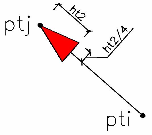
Figure 15 – AuPolyline side graphics.
2 comments :
How can i construct a polyline..
by getting inputs from the user programmatically
Hi adline,
The polyline is a complex entity which means that it is composed by subentities (vertexes).
Take a look at the sample:
\ObjectARX 2007\samples\database\complex_dg
The is a function called createPolyline() that shows how to create a polyline.
You may add some code to get each point from user (storing them into an AcGePoint3dArray) and then create the polyline yourself.
Note that the AcDbPolyline constructor can receive an AcGePoint3dArray with the desired vertexes.
Regards.
Post a Comment